





Food Industry


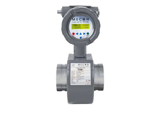
mag-flux® T4
Magnetic-inductive fire pump meter specifically for use in stationary fire safety applications – Sprinkler systems

MECON has upgraded flow meters for sprinkler system applications with the mag-flux® T4, offering a solution with a fast 16-bit microcontroller and an electrical 4 – 20 mA output. As a result, the mag-flux® T4 is easy to integrate in existing remote monitoring systems, and the measurements can be evaluated in a control centre. For installation, the device offers an impressive range of connection options – e.g. flange, threaded or groove connections. In fact, the mag-flux® T4 fire pump test meter is the only product with a VdS-certificated groove connection. The measurement accuracy is ±0.5%.
Description
Area of application:
Magnetic-inductive flow sensors (MID) are precision measurement devices, suitable for linear flow measurement of almost all electrically conductive liquids. Their magnetic field allows them to be used for flow speeds up to 10 m/s (32.8 ft/s) and for a minimum conductivity of 20 µS/cm in synchronised d.c. fields. According to the intended use per the VdS directive, this magnetic-inductive flow meter (MID) must not be used for process control.
The mag-flux® T4 fire pump test meter is used in the following industries:
- Fire safety – Sprinkler systems
Advantages of the mag-flux® T4 magnetic-inductive flow meter with VdS approval:
- Reliability (long-term stability, service life)
- Minimal maintenance requirements
- Simple commissioning
- Simple interpretation of measurements
- Simple commissioning
- Manufacturer’s application expertise
- Short lead times
Special features of the fire pump test meter for sprinkler systems :
- Fully welded steel fitting
- VdS certificate 2344, 2100-29
- Fast signal processing with 16 bit micro-controller
- Fixed measurement ranges
- Compact or separate design
- Easy to install with coupling connection
- Short inlet and outlet section
- Simple electrical connection via M12 plug connector
- 4-20 mA output
Measuring tube connections:
- nominal sizes from 2″ / DN 50 to 10″ / DN 250 (coupling connection)
- nominal sizes from G ½ bis G 2 (threaded connection)
- Nominal sizes from ½“ / DN 15 to 10“ / DN 250 (EN 1092-1)
- Nominal sizes from ½“ / DN 15 to 10“ / DN 250 (ANSI B16.5)
Downloads
